
Facility


Purpose of the beamline (BL09A, BL09B, and BL09C)
The purpose of the beamline BL09A is to carry out microanalysis, surface analysis, and bulk analysis for various industrial materials with the use of high brilliant light source of the Long Undulator (11m) and high resolution monochromator. Now, X-ray absorption spectroscopy (NEXAFS) and X-ray photo emission spectroscopy (XPS) at the soft X-ray region are available. A Soft X-ray emission spectroscopy (XES) system with concave grating monochromator is under construction.
BL09B and BL09C is branched beamline of BL09. BL09B is for the EUV interference lithography to evaluate EUV resist in 1X nm resolution. BL09C is for the in-situ contamination thickness measurement from the resist outgassing during EUV irradiation. Both work is very significant to transfer EUVL technology into high volume manufacturing.
BL09A
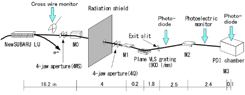
Schematic diagram of BL09A
Specifications of the mirrors (BL09A)
Mirrors
The geometrical configuration of the mirrors in the beamline, BL9a, is shown in Fig. 1. M0 and M3 mirrors are used for deflection and focusing in the horizontal direction. M1 and M2 mirrors are used for deflection and focusing in the vertical direction. Monk-Gillieson type monochromator is configured by M1 and a plane VLS grating. The maximum acceptances of the undulator light are 0.64 mrad for horizontal direction and 0.27 mrad for vertical direction. The acceptances are limited by a four jaw aperture (4Q) placed at the upstream of the M1 mirror. There is another four jaw aperture (4ws) equipped at the upstream of the M0 mirror (15.2 m position) since May 2001, which is used for the alignment of the undulator light. Specification of mirrors in BL9a is summarized in the Table below.
| Mirror | M0 | M1 | M2 | M3 |
|---|---|---|---|---|
| configuration | spherical | spherical | spherical | toroidal |
| size(LxWxT) | 200x30x40 | 100x30x40 | 700x40x40 | 35x25x25 |
| radius of curvature | 250.511m | 69.892m | 47.768m | 2.3m x 10m |
| incidence angle | 3 deg | 3 deg | 3 deg | 5 deg |
| material | Si | SiO2 | SiO2 | SiO2 |
| coating | Ni | Ni | Au | Au |
Filter
A Be membrane filter is equipped at the downstream of the M2 mirror.
Monochromator
The specification of the monochromator is summarized in the Table below.
| Mount type | Monk-Gillieson type |
|---|---|
| Grating | Plane VLS grating, 300, 900, 1200 (l/mm) |
| Energy range | 70 – 750eV |
| Energy resolution ΔE/E | ~3000 |
Spectrum of BL09A
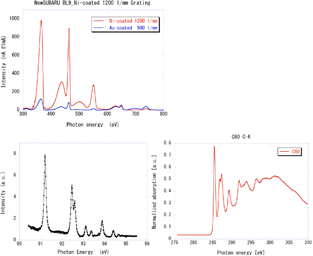
Figure 2 shows the spectra of the long undulator radiation. The intensity (vertical axis in Fig. 2) is represented with the output current of the photodiode placed at the downstream of the exit slit, which is normalized by the storage electron current. The intensity of the photon energy greater then 300 eV was improved excellently by introducing Ni-coated grating with grove density of 1200 l/mm.
 go to page top
Specification of the endstation (BL09A)
| Function | soft X-ray analysis |
|---|---|
| sample | 16 x 25.5mm Cu sample holder load lock system |
| Manipulator | x,y,z,θ axes, able to measure sample current |
| E-analyzer | CHA, VG100AX |
| Beam size | 800(w) x 200(h) μm |
| Vacuum pressure | 5 E-6 Pa, differential pumping @ upstream |
| Number of Photons | 1.2 E13 photons/sec, at 95 eV, Ie=40mA |
Collaboration etc. (BL09A)
It is possible if the content and condition of the measurement agree with the BL specification. The user who can use not only the purpose of taking data by using BL but also a collaboration research to develop a new analysis technique is preferable
Instruments for shared use (BL09A)
EUV irradiation and in situ surface analysis system.
BL09B
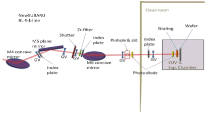
To evaluate the EUV resist in 1X nm resolution, EUV interference lithographic exposure tool is installed at the class 100 clean room at the end station of BL09B beamline. The 10.8-m-long undulator was employed as a light source of the BL9 beamline. By tuning the undulator gap, the EUV monochromated wavelength of 13.5 nm can be produced by the undulator, and the flux intensity of the EUV light is approximately 1,000 times higher than that from the bending magnet as a light source. In the optics design concept of the EUV-IL beamline, to increase the exposure throughput of the EUV-IL, the number of the optical mirrors reduced as much as possible. And then, reducing the exposure time, it can prevent from the vibration effect.
Configuration
Principle of the Interference Lithography
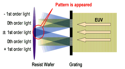
The principle of the interference lithography based on the two-luminous-flux interference exposure using the two-window transmission grating is shown in Fig.2 By one grating, coherent EUV light is diffracted to the 0th, ±1st, ±2st, …. order lights. As shown in Fig., at the interference point of 1st-order and -1st-order diffracted lights, the interference fringes were created. Since the pitch the interference fringes have a half pitch size of the diffraction grating, replication pattern pitch of the resist pattern has a half pitch size of the diffraction grating.
BL09C
The in-situ contamination thickness measurement by the EUV resist outgassing during EUV irradiation with the practical EUV light intensity which is same order that in high volume manufacturing can be carried out. The electron beam is used for the contamination evaluation from the EUV resist outgass. It is significant to compare the contamination growth between EUV and EB irradiation. To reduce the influence of carbon contamination growth, which is the origin of the resist outgassing during extreme ultraviolet (EUV) exposure, it is necessary to study the relationship between the outgassing species from the resist and carbon contamination growth during EUV exposure. Thus a novel evaluation system which enable the measurement of the carbon contamination thickness on a Mo/Si multilayer witness sample by in-situ ellipsometry in the resist outgassing environment under EUV exposure is installed at the BL09C beamline.
Contamination Evaluation System
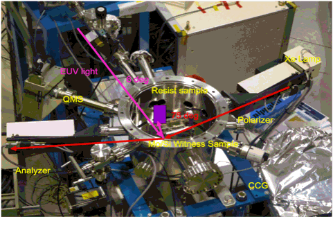
Figure shows the configuration of the experimental setup for the novel resist evaluation system. This system consists of a Mo/Si MLs mirror stage, a wafer of the resist sample, a turbomolecular pump, a quadruple mass spectrometer and an in-situ ellipsometer. SR light illuminates a Mo/Si ML mirror first, at the incidence angle of 6 degrees. After the incident light reflected by the Mo/Si ML is irradiated, outgases produced from the resist upon EUV irradiation will evaporate in the vacuum chamber. Outgas species can be detected using a M-QA200F quadrupole mass spectrometer (ANELVA). Carbon contaminates the Mo/Si ML mirror. The thickness of contamination can be measured by in-situ ellipsometry (SOPRA). A xenon lamp is employed as the light source of ellipsometry, and the xenon light was irradiated onto the contamination of the Mo/Si ML witness sample at an incidence angle of 75º. The xenon light reflected from the Mo/Si ML witness sample was monochromated at a wavelength from 250 to 800 nm by the ellipsometric spectrometer. Then the ellipsometric analysis of the contamination thickness can be carried out.
ミラー仕様(BL09C)
| ミラー名 | M0 | M1 | M4 | M5 | M6 | M7 | M8 |
|---|---|---|---|---|---|---|---|
| 形状 | 凹球面 | 凹球面 | 平面 | 凸球面 | 平面 | 凹球面 | 凹球面 |
| コーティング材料 | Pt | Pt | Ru | Ru | Pt | Pt | Pt |
| 入射角(度) | 3 | 3 | 9 | 3 | 3.5 | 9 | 6 |
フィルター仕様(BL09C)
標準フィルター:Zr(退避も可能)
分光器の仕様(BL09C)
| Monochromator | 定偏角不等間隔平面回折格子 | |
|---|---|---|
| 定偏角 | 168度 900 /mm |
エンドステーション仕様(BL09C)
BL09Cのエンドステーションには、干渉露光装置が設置されています。
コヒーレンス長(干渉露光用透過型回折格子)
| ピンホール直径 (μm) | コヒーレンス長 (μm) |
|---|---|
| 25 | 544 |
| 10 | 1173 |


